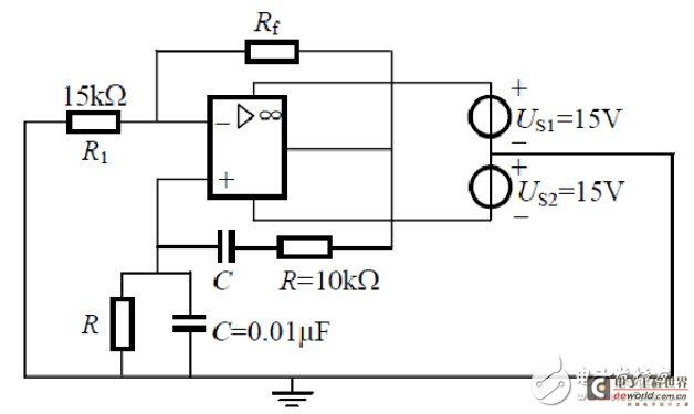
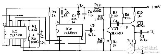
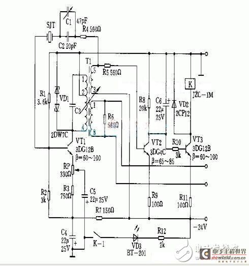
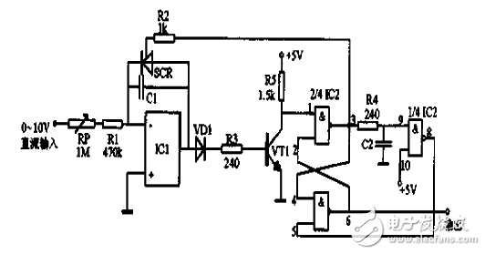
All instruments that generate test signals are collectively referred to as signal sources. The oscillating circuit of the signal generator, also known as the signal generator, is used to generate an electrical test signal for the particular parameters required by the circuit under test. In the test, research or adjustment of electronic circuits and equipment, in order to determine some electrical parameters of the circuit, such as measuring frequency response, noise figure, voltmeter degree, etc., it is required to provide electrical signals in accordance with the specified technical conditions to simulate in practice. The excitation signal of the device under test used in the work. When a steady-state characteristic measurement of the system is required, a sinusoidal signal source of known amplitude and frequency is used. When testing the transient characteristics of the system, it is necessary to use a rectangular pulse source with a known leading edge time, pulse width and repetition period. And the parameters of the signal source output signal, such as frequency, waveform, output voltage or power, can be precisely adjusted within a certain range, with good stability and output indication. This article has collected several classic signal generator circuits to provide reference for engineers and electronic enthusiasts to design signal generation circuits. First, sinusoidal signal generation circuit The Wien bridge oscillator is the most classic sinusoidal signal generator. Its advantages are: not only the oscillation is stable, the waveform is good, but the oscillation frequency can be conveniently adjusted continuously in a wide range. The RC series-parallel frequency-selective network and amplifier can be combined to form an RC oscillating circuit, and the amplifier component can be an integrated operational amplifier. The RC series-parallel frequency selection network is connected between the output terminal of the operational amplifier and the non-inverting input terminal to form a positive feedback, and the resistor connected between the output end of the operational amplifier and the inverting input terminal constitutes a negative feedback. The positive feedback circuit and the negative feedback circuit form a Wien bridge bridge. Circuit diagram of a sine wave generator composed of a bridge frequency selection circuit and an amplifier Second, the pulse signal generator circuit In the detection of many devices, a pulse signal source is required, but the standard pulse signal source circuit is complicated and the price is high, which is difficult for electronic enthusiasts to do. To this end, this paper designs a simple pulse signal generator, the effect is ideal. The signal generator mainly uses two TTL integrated circuits (74LS00 and 74LS221). Since the transistors in the TTL work in the saturation region, the circuit works stably, the input and output impedances are relatively low, and it is not easily interfered by the surrounding stray electromagnetic fields, and the switching speed is fast. The power consumption is low, and the anti-interference degree of the circuit is improved. 74LS00 consists of four NAND gates, three of which form a square wave oscillating circuit. The output of the last NAND gate is fed back to the input of the first NAND gate, so after an odd number of inversions, the signal phase is reversed. The circuit is oscillated back and forth, and the resistor and the capacitor are connected to obtain an oscillating circuit with adjustable frequency. Third, high frequency signal generator High frequency, 30 to 300 MHz very high frequency signal generator with a frequency of 100 kHz to 30 MHz. An LC tuned oscillator is typically used and the frequency can be read by the dial scale of the tuning capacitor. The main purpose is to measure the technical specifications of various receivers. The output signal can be amplitude modulated or frequency modulated with an internal or external low frequency sinusoidal signal to attenuate the output carrier voltage to less than 1 microvolt. The high frequency signal generator is composed of a high frequency quartz crystal oscillation circuit and an alarm circuit. The working principle is as follows: the oscillator circuit is composed of a voltage regulator VD1 and a triode VT1, a quartz crystal resonator SJT, a capacitor C1, a C2 parallel resonant tank circuit, and other resistors, capacitors and the like. The oscillator is a single-tube tuning variable converter feedback oscillation circuit. In the feedback loop, a quartz crystal resonator SJT is connected in series, the oscillation frequency is operated in a fixed capacitance C2 of the quartz crystal resonator connected in series, and the air trimming capacitor C1 is used for compensation. Quartz crystal resonators get the best excitation power. Fourth, low frequency signal generator The low frequency signal generator includes a sine wave generator in the range of audio (200 to 20,000 Hz) and video (1 Hz to 10 megahertz). The main oscillation stage generally uses an RC type oscillator, and a difference frequency oscillator can also be used. In order to facilitate testing the frequency characteristics of the system, it is required that the output amplitude frequency characteristic is flat and the waveform distortion is small. This circuit has good linearity and accuracy. When the output is 1000 pulses per second, the error is only 1%. If 10 pulses per second, the error can be reduced to 0.001%. Since the cathode of the thyristor SCR is the summing point connected to the operational amplifier. Therefore, negative voltage control should be used. For positive input voltage, you can reverse the input and input. The circuit reset is done by the RS flip-flop and the delay inverter. Usually the output of the flip-flop Q is low, so the thyristor SCR is turned off, and the output of the integrator is applied to the base of the transistor VT1 through the diode VD1. When the integrator output reaches approximately 1.4V, the transistor turns on, setting the flip-flop. At this time, the Q output of the flip-flop becomes a high level, the thyristor SCR is turned on, and the integrating capacitor is discharged. The high level of the Q output is reset by a delay of 1us and the flip-flop is reset. When the integrating capacitor C is discharged to about 0.7V, the thyristor is turned off, so the second integration period begins.
Household products refer to the types of appliances that humans need to maintain their normal lives, engage in production practices and carry out social activities. For example, plastic drink ware, plastic tableware, etc., household products are not only a simple functional substance product, but also a widely popular mass art. It is necessary to satisfy certain specific purposes and to satisfy people`s appreciation. In the process of contact with the use of some of the aesthetic pleasure and lead to a rich association of the spiritual needs.
Our team can provide customized services for customers' individual needs.
Plastic Drink ware
Plastic Tableware
Plastic Drinking Cups,Plastic Drinkware,Plastic Dishes,Clear Plastic Plates Triple C International (Shenzhen) Co.,Ltd. , https://www.ccc-triple.com